")
")
| Issue |
Radioprotection
Volume 55, Number 3, July-September 2020
|
|
|---|---|---|
| Page(s) | 179 - 185 | |
| DOI | https://doi.org/10.1051/radiopro/2020052 | |
| Published online | 29 mai 2020 | |
Article
Dose comparative study between two different 3D mobile intra-operative systems
1
Service de radiologie, Hôpitaux Universitaires de Genève,
Rue Gabrielle-Perret-Gentil 4,
1205
Genève, Switzerland
2
Institute of Radiation Physics,
Rue du Grand Pré 1,
1007
Lausanne, Switzerland
3
Service d’ingénierie biomédicale, Hôpitaux Universitaires de Genève,
Rue Gabrielle-Perret-Gentil 4,
1205
Genève, Switzerland
* Corresponding author: Cette adresse e-mail est protégée contre les robots spammeurs. Vous devez activer le JavaScript pour la visualiser.
Received:
10
February
2020
Accepted:
29
April
2020
Abstract
3D imaging devices, when coupled to an image guided surgery system, allow for a more precise surgical approach than classical C-arms. Nevertheless, the exposure to radiation of both patient and staff remains a concern and therefore the choice of imaging device plays an important role. Two 3D imaging systems, an imaging mobile device with an O-ring geometry and an imaging mobile device with a C-arm geometry, have been compared in terms of absorbed doses to organs as well as ambient dose equivalent. Absorbed organ doses were evaluated for thoracic and pelvic examinations using TLDs placed within a CIRS anthropomorphic phantom representing an adult woman. Equivalent ambient dose measurements were performed at various positions in the room around the X-ray system using a calibrated dose rate meter. Results suggest that the O-ring system exposes both patient and staff to higher levels of radiation than the C-arm system. Indeed, organ absorbed doses were found to be 3.5 and 1.7 higher for the O-ring system than for the C-arm system for the same thoracic and pelvic explorations respectively. Concerning the ambient dose equivalent, it was found that for a single 3D image acquisition at a radial distance of one meter from the isocentre, measurements for the O-ring system were approximately 30% larger than the C-arm system.
Key words: image guided surgery / 3D mobile intra-operative systems / dosimetry / cone beam CT
Present adresse: Département Diagnostic, Service de radiologie, Hôpitaux universitaires de Genève, Rue Gabrielle-Perret-Gentil 4, CH-1205 Genève.
© SFRP, 2020
1 Introduction
The number of mobile X-ray medical devices for real-time 2D and 3D imaging is growing in the operating room (Miller, 2008, 2009). Furthermore, examinations in 3 dimensions allow for a more precise surgical approach, especially when coupled with image guided surgery systems (IGS or navigation) (Kendoff et al., 2008; Gelalis et al., 2012). These technologies were initially used in adult orthopaedics surgery and neurosurgery, but have been expanded to the paediatric field (Temple and Langer, 2003; Larson et al., 2012). These 3D imaging systems not only provide volumetric images crucial for certain surgical interventions, but also allow surgeons to immediately verify the results of the surgery with a perioperative 3D image without having to wait for a postoperative CT scan.
To our knowledge, three manufacturers currently offer mobile 3D X-ray technologies intended for the operating room. Two of the three companies make mobile C-arms fitted with flat panel detectors. The third company offers a ring-shaped cone beam CT with a flat panel detector. Even though the benefits of a 3D imaging coupled to a navigation system are clear, the exposure of the patient to radiation remains a concern. These technologies subject patients and staff to ionizing radiation; it is essential to know which device is optimal in terms of radiation protection.
A measurement protocol has been established to compare one mobile C-arm system to one ring-shaped cone beam CT system in terms of different dosimetric quantities for both patient and staff during a 3D acquisition. The exposure of the patient was evaluated for each of the two intra-operative systems by measuring the absorbed doses to organs of an anthropomorphic phantom representing a patient. The exposure of the staff was assessed by measuring the ambient dose equivalent H*(10) values for each of the two intra-operative systems. Moreover, the ambient dose equivalent measurements performed allowed us to optimize the protection of the staff.
2 Materials and methods
The systems consist of a gantry with both an X-ray generator and an X-ray flat panel detector, as well as a mobile display station equipped with two screens. A single cable provides power and signal for both units. Physically, the main difference between the two systems is the gantry’s geometry. The system offering a ring-shaped cone beam CT, produced by Medtronic (Medtronic, Minneapolis, USA), is called O-Arm® and has a telescopic door that can be opened to allow lateral access of the patient and closed for image acquisition. Here we will be referring to this system as the O-ring system. The mobile radioscopy unit tested in this study, the Ziehm RFD 3D produced by Ziehm (Ziehm Imaging GmbH, Nüremberg, Germany), consists of an open support structure. Here we will be referring to this system as the C-arm system. Figure 1 shows these differences as well as their image acquisition geometry.
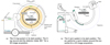 |
Fig. 1 Measurement geometries for the O-ring system (a) and the C-arm system (b). |
2.1 Acquisition parameters
With the O-ring system, the acquisition parameters are divided into 4 anatomical localisations (head, chest, hip and extremity), each subdivided into 4 patient sizes (S, M, L, XL). These correspond to different tube current-time products, with units of mAs. For our measurements, the small thorax and hip protocol were selected, as this reflects the parameters used clinically at our institution for the average woman. For both anatomical localisations, the parameters are the same consisting of a fixed tube voltage and tube current-time product of 120 kV and 128 mAs, with a pulse width of 10 ms. The system acquires a total of 400 images at a rate of 30 images per second over 360°, for an acquisition time of approximately 13 s.
The main difference when comparing the C-arm system to the O-ring system is that acquisition parameters for the C-arm system are adapted by the automatic exposure control (AEC). Here, the default factory settings of 100 kV, 8 images per second and pulse width of 23 ms were selected, also reflecting common clinical practice. For the first part of the image acquisition, the gantry displaces laterally, with the tube current fixed at 15 mA. During the 165° rotation, the tube current varies using AEC, in our case varying between 3.4 to 15 for the thoracic and 7.2 to 44.5 mA for the pelvic protocols. The final lateral acquisition phase occurs at the last mA used during the rotation. Table 1 highlights some of the technical parameters that differ in direct relation to the use and performance of the systems including the different dosimetric quantities: computed tomography index (CTDI) and dose length product (DLP) for the O-ring system and dose area product (DAP) for the C-arm.
Technical parameters for both systems.
2.2 Organ absorbed doses
Absorbed organ doses were evaluated using thermoluminescent pellets (MCP-n TLDs, TLD Poland, Krakow, Poland) placed within an anthropomorphic phantom (CIRS-702, CIRS, Norfolk, VA, USA) representing a woman of 160 cm and 55 kg (see Fig. 2). The phantom is made using different materials simulating bone, brain, lung, breast and soft tissue, with differences in linear attenuation coefficients between the materials and human tissue below 1%. The phantom consists of 38 slices 25 mm thick, and contains holes for the TLDs distributed within the different target organs (see Fig. 2).
For a 3D acquisition on the thorax, the phantom was placed in the prone position with the radiation beam centred on slice 17 of the anthropomorphic phantom. For pelvic measurements, the phantom was placed on its back, with the beam centred on slice 29. The isocentre of the device is placed in the middle of the selected slice. All measurements were performed on a radio-transparent surgical bed (Jupiter, Trumpf, Saalfeld, Germany or Otesus, Maquet, Rastatt, Germany). For measurements with the C-arm system, 40 acquisitions were made to accumulate sufficient dose. In the case of the O-ring system, 30 acquisitions were made. A larger number of acquisitions were performed with the C-arm system because lower doses were expected with this technology. All results were then normalized for a single 3D acquisition.
The absorbed dose for each organ was obtained from the TLD readings placed in that organ. In cases where more than one TLD was placed in a specific organ, the organ’s absorbed dose was calculated as the mean value of the TLD measurements. The organs where measurements have been performed are: brain, left/right eye, oesophagus, thyroid, left/right lung, left/right breast, heart, liver, spleen, stomach, pancreas, left/right kidney, colon and uterus. The calibration and energy correction factors were applied to obtain the absorbed organ dose.
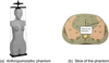 |
Fig. 2 Anthropomorphic phantom representing an adult female (a) and a slice of the phantom with holes (b) for the TLDs placement on the right. |
2.3 Ambient dose equivalent
Equivalent ambient dose H*(10) measurements were performed at various distances from the isocentre of the X-ray system ranging from 24 to 322 cm simulating the different positions of the staff in the room. The measurements were done for a 3D pelvic acquisition as the scattered radiation was expected to be higher than for a 3D thoracic acquisition. For this purpose, a calibrated dose rate meter was used (AT1123, APVL, Saint-Cyr-sur-Loire, France). The measurement points were positioned on the plane of the isocenter following 8 different axes at 45° between each other. In total 47 measurement points were chosen for the O-ring system cartography and 27 for the measurements with the RFD 3D, with each point measured three consecutive times. The mean value was taken to represent the ambient dose equivalent. A smaller amount of measurements points was considered for the C-arm system due to the different room size. A Python 3 script using the Numpy library was used to construct the isodose map, using a cubic spline interpolation algorithm.
2.4 Uncertainties
Uncertainties were calculated in accordance with the BIPM’s Guide to the Expression of Uncertainty in Measurement (JCGM-W, 2008) and expressed with a coverage factor k = 2, with the largest uncertainty associated with the energy correction factor.
3 Results
The dosimetric quantities obtained for a 3D acquisition with the O-ring system and the C-arm system are summarized in Table 2.
With the O-ring system, no difference in CTDI or DLP values were obtained between a 3D acquisition on the thorax or on the pelvis. On the other hand, the DAP of the C-arm system is higher by a factor of 3 for an acquisition on the pelvis.
The results for the organ absorbed doses when performing a thorax acquisition with the O-ring system and the C-arm system are shown in Figure 3. The error bars in the graphs indicate the uncertainty of the TLD measurement. Values obtained are between 4.90 μGy and 1.88 mGy for the C-arm system and between 22.1 μGy and 7.49 mGy for the O-ring system. The less exposed organ in both cases is the brain. The most exposed organs are the liver and breast for the C-arm system and breast and lungs for the O-ring system.
The results for the organ absorbed doses when performing a pelvic acquisition with the O-ring system and the C-arm system are shown in Figure 4. The error bars in the graphs indicate the uncertainty of the TLD measurement. Values obtained are between 1.90 μGy and 3.45 mGy for the C-arm system and between 4.10 μGy and 5.88 mGy for the O-ring system. The less exposed organ in both cases is the brain. The most exposed organs are the colon and uterus for the C-arm system and for the O-ring system.
The dose ratio between the O-ring system and the C-arm system are given for different organs in Tables 3 and 4 for both thoracic and pelvic irradiation respectively. The organ absorbed doses are higher for the O-ring system than for the C-arm system, with a mean organ absorbed dose ratio of 3.5 for the thoracic irradiation and 1.7 for the pelvic irradiation.
The results of the ambient dose equivalent H*(10) measurements, representing medical staff potential effective dose, are shown in Figure 5 for a single 3D acquisition of the pelvic region using the O-ring system (left) and the C-arm system (right). The dots shown in Figure 5 represent the measurement points.
The ambient dose equivalent is between 2 and 15 times higher for the O-ring system than for the C-arm system. At 80 cm from the isocentre along the axis 45° from the patient axis, the equivalent dose given by the O-ring system is 58 μSv and approximate 5 times smaller for the C-arm system, i.e. 11 μSv.
Dosimetric quantities resulting from a 3D acquisition of the thoracic and pelvic region using the O-ring system and C-arm system systems.
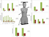 |
Fig. 3 Organ absorbed doses for the anthropomorphic phantom for a 3D acquisition with the beam centred on the thorax (Sect. 2 of the phantom). |
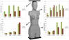 |
Fig. 4 Organ absorbed doses for the anthropomorphic phantom for a 3D acquisition with the beam centred on the pelvis (Sect. 4 of the phantom). |
Dose ratios between the O-ring system and the C-arm system for a thoracic acquisition.
Dose ratios between the O-ring system and the C-arm system for a pelvic acquisition.
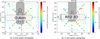 |
Fig. 5 Ambient dose equivalent H*(10) measurements for the O-ring system (a) and the C-arm system (b) for a single 3D pelvic acquisition. |
4 Discussion
The O-ring system uses the same 3D acquisition parameters independently of the anatomical position of the acquisition, i.e. thorax or pelvis. This can be seen from the values of CTDI and DLP shown in Table 2. Indeed, there is no modulation on the current (fixed value of current-time product at 128 mAs), no change in kV (fixed at 120 kV). In contrast, the C-arm system modulates the current; consequently, the DAP is higher by a factor of 3 for an acquisition on the pelvis due to the need of a larger number of photons to compensate for the higher absorption in the pelvic area as compared to the thoracic area.
For both systems the dose absorbed by the organs situated in the primary beam are much larger, as expected, than the dose for those organs situated in the scattered beam. These decrease as the distance from the primary beam area increases. Moreover, the doses delivered by the O-ring system are higher for most of the organs than those delivered by the C-arm system, as observed by computing the organ dose ratio for these two systems (see Tabs. 3 and 4). Indeed, there are only few exceptions corresponding to the organs placed at the left side of the body and only for the case of the pelvic acquisition. This is clearly due to the fact that the distance between the tube of the C-arm system and the left side of the skin of the patient is small, much shorter than for the O-ring system.
The results obtained for the ambient dose equivalent are in good agreement with the ones obtained for the absorbed organ doses, lower doses for the C-arm system than for the O-ring system. Whereas the O-ring system ambient dose equivalent is more symmetric around the table, as described in Pitteloud et al.’s publication (Pitteloud et al., 2016), the distribution around the couch when doing a 3-dimensional image acquisition using the C-arm system is more heterogeneous. This difference is attributed to the fact that the X-ray tube spends a greater amount of time on the side opposite to the control panel. These results are in good agreement with those discussed in the white paper provided by Lochner et al., where a dosimetric comparative study using a CTDI phantom was performed on an O-ring system, a C-arm system and a NeuroLogica BodyTom (Lochner et al., 2018). Furthermore, during a 3D image acquisition, the arm not only performs a semi-rotation, but also a diagonal displacement. It is therefore suggested to personnel who remain in the operating theatre during a 3D acquisition to position themselves on the same side as the controls.
Our study was centred only on the dosimetric comparison of both systems; image quality has not been evaluated. This last aspect should be considered for a more complete comparison. However, parameters used for acquisition were the ones used in clinical practice, suggesting that image quality was sufficient in both cases. Still, information about image quality is given in the white paper provided by Lochner et al. Moreover, the results have been obtained in the specified conditions, an optimisation of the protocols may change the results.
5 Conclusion
By applying an identical measurement protocol on two mobile 3D imaging systems absorbed organ doses and ambient dose equivalent measurements were determined. For the specific protocols tested and because of the different measurement geometries, as well as acquisition parameters of these imaging devices, dose distributions inside of the patient as well as ambient measurements are markedly different with higher doses associated to the use of the O-ring system compared to the C-arm system. These results should be considered when considering the acquisition of a 3D imaging device.
References
- Gelalis I et al. 2012. Accuracy of pedicle screw placement: A systematic review of prospective in vivo studies comparing free hand, fluoroscopy guidance and navigation techniques. Eur. Spine J. 21(2): 247–255. [CrossRef] [PubMed] [Google Scholar]
- JCGM-W. 2008. Guide to the expression of uncertainty in measurement. Geneva: International Organization for Standardization. [Google Scholar]
- Kendoff D et al. 2008. Value of 3D fluoroscopic imaging of acetabular fractures comparison to 2D fluoroscopy and CT imaging. Arch. Orthop. Trauma Surg. 128(6): 599–605. [Google Scholar]
- Larson A et al. 2012. Pediatric pedicle screw placement using intraoperative computed tomography and 3-dimensional image-guided navigation. Spine 37(3): E188–E194. [CrossRef] [PubMed] [Google Scholar]
- Lochner L, Meier A, Stelzer G, Packard K. 2018. Dose comparison between Ziehm Vision RFD 3D and medtronic O-arm 02. White Paper No. 39. [Google Scholar]
- Miller D. 2008. Overview of contemporary interventional fluoroscopy procedures. Health Phys. 95(5): 638–644. [CrossRef] [PubMed] [Google Scholar]
- Miller D. 2009. Interventional fluoroscopy: reducing radiation risks for patients and staff. J. Vasc. Interv. Radiol. 20(7): S274. [CrossRef] [PubMed] [Google Scholar]
- Pitteloud N, Gamulin A, Barea C, Damet J, Sans-Merce M. 2016. Radiation exposure using the O-arm surgical imaging system. Eur. Spine J. 26(3): 651–657. [CrossRef] [PubMed] [Google Scholar]
- Temple M, Langer JC. (2003). Image-guided surgery for the pediatric patient: Ultrasound, computerized tomography, and magnetic resonance imaging. Curr. Opin. Pediatr. 15(3): 256–261. [CrossRef] [PubMed] [Google Scholar]
Cite this article as: Sans Merce M, Pitteloud N, Savoye F. 2020. Dose comparative study between two different 3D mobile intra-operative systems. Radioprotection 55(3): 179–185
All Tables
Dosimetric quantities resulting from a 3D acquisition of the thoracic and pelvic region using the O-ring system and C-arm system systems.
Dose ratios between the O-ring system and the C-arm system for a thoracic acquisition.
Dose ratios between the O-ring system and the C-arm system for a pelvic acquisition.
All Figures
|
Fig. 1 Measurement geometries for the O-ring system (a) and the C-arm system (b). |
| In the text | |
|
Fig. 2 Anthropomorphic phantom representing an adult female (a) and a slice of the phantom with holes (b) for the TLDs placement on the right. |
| In the text | |
|
Fig. 3 Organ absorbed doses for the anthropomorphic phantom for a 3D acquisition with the beam centred on the thorax (Sect. 2 of the phantom). |
| In the text | |
|
Fig. 4 Organ absorbed doses for the anthropomorphic phantom for a 3D acquisition with the beam centred on the pelvis (Sect. 4 of the phantom). |
| In the text | |
|
Fig. 5 Ambient dose equivalent H*(10) measurements for the O-ring system (a) and the C-arm system (b) for a single 3D pelvic acquisition. |
| In the text | |
Current usage metrics show cumulative count of Article Views (full-text article views including HTML views, PDF and ePub downloads, according to the available data) and Abstracts Views on Vision4Press platform.
Data correspond to usage on the plateform after 2015. The current usage metrics is available 48-96 hours after online publication and is updated daily on week days.
Initial download of the metrics may take a while.