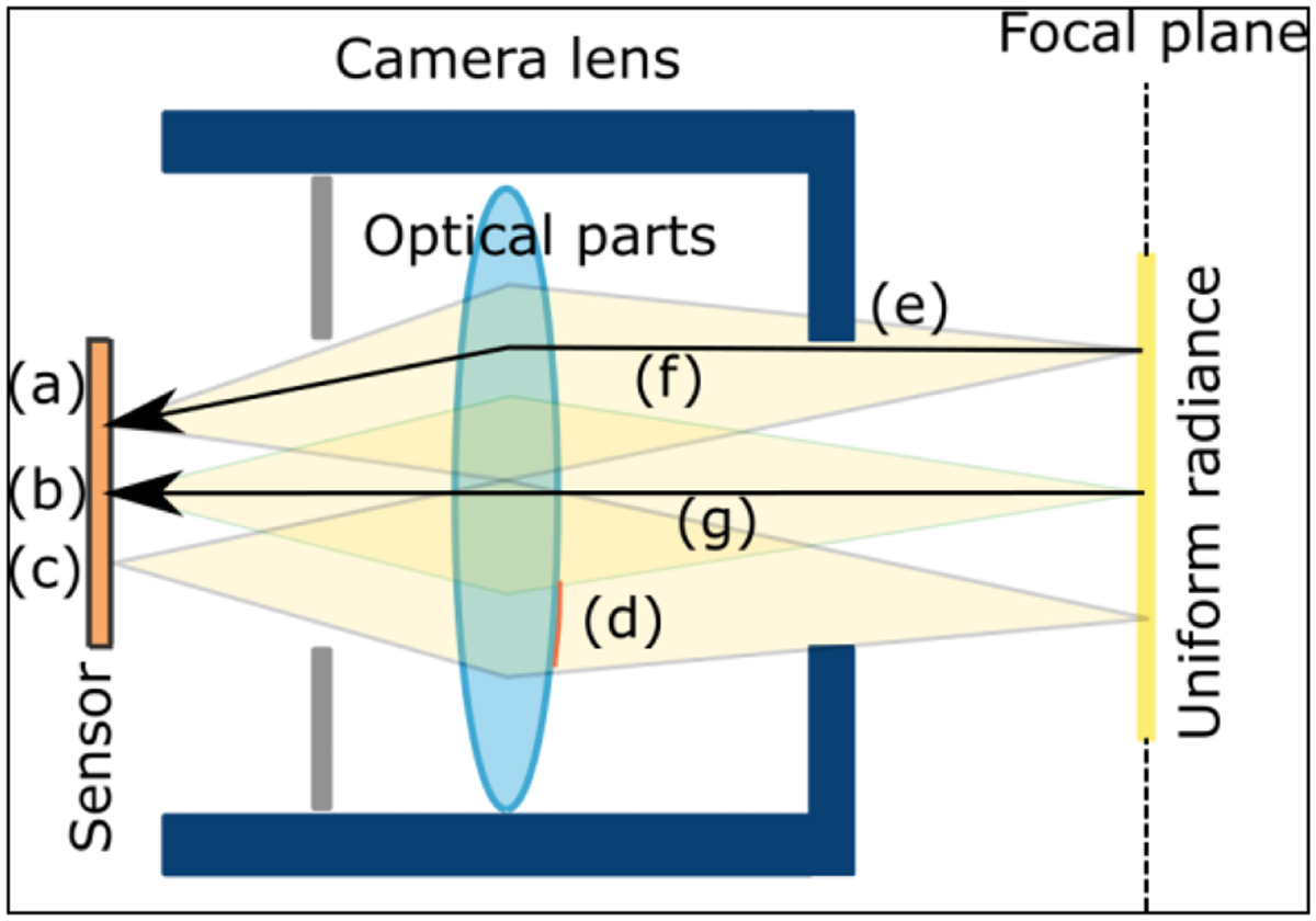
Fig. 7

Download original image
Schematic examples of non-uniformities in the sensor reaction to a uniform radiance in the focal camera plane. (a) and (c) are pixels in the border of the sensor, while (b) is at its center. In yellow: the optical paths from the observed radiance to the (a), (b) and (c) pixels. Optical vignetting reasons: (a) receives less light than (b) because light is partially occluded at (e); pixel irradiance differ between (a) and (b) because of different optical paths (e.g., (f) and (g)) from observed radiance to pixels. Vignetting due to defects: less light reaches the sensor at (c) than elsewhere due to dirt at (d).
Current usage metrics show cumulative count of Article Views (full-text article views including HTML views, PDF and ePub downloads, according to the available data) and Abstracts Views on Vision4Press platform.
Data correspond to usage on the plateform after 2015. The current usage metrics is available 48-96 hours after online publication and is updated daily on week days.
Initial download of the metrics may take a while.


